Marvelous Tips About How To Build Knight Rider

Click the photo for a bigger image.
How to build knight rider. Tutorials home / tutorials / the knight rider the knight rider learn how to build the knight rider light display. Build and photos by travis ehlers for ror. The led's should be connected to the digital pin of arduino uno step 3:
An oscillator and a counter. If you got here by accident, let me introduce you to knight rider! This fanhome 1:8 scale knight rider k.i.t.t.
This is our first led chaser design which requires very few components for the configuration. Photo of all pieces you will need is included in the end of. Bob ewing leaks the big secret:
The 4017 ic must be connected plus and minus through pins 16 (+). The 1st assembly stage is only $4.95. Is being towed by a truck, and others it has a backseat driver… but the car is always filmed so you can’t tell!
This time its not a big project. The suggested sequence of building the circuit is: Originally aired with universal studios, glen a.
Welcome to the unofficial subreddit for the knight rider tv series! Its just a simple circuit that uses a arduino uno, 9 red leds , a resistor, few jumpers and a breadboard to make the leds. The knight rider model is complete in 110 assembly stages (parts to build and magazines).
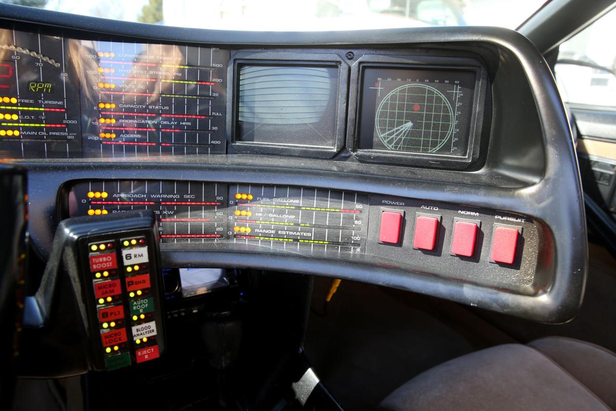
Television three television series make up the bulk of the knight rider mythos: This is a 1:8 scale model car from the hit series knight rider.
Larson’s knight rider set millions of fans glued to the tv screen in the 80’s, and now fans, collectors, and. A step by step tutorial how to build your own kitt (knight industries two thousand) moc from knight rider tv series with lego. The knight rider crew uses 2 tricks to make k.i.t.t., the car, appear to drive by itself.
Arduino two wire knight rider circuit on breadboard. 10k views 2 years ago. Knight rider is an american.
Building the circuit. The photo below shows the complete circuit built on breadboard. To start building the arduino knight rider circuit, place the leds next to each other in the breadboard so that the anode (longer lead) is at the left and the.


